The Arduino Mega 2560
This 128kByte, 16MHz AtMega board has 4 UARTS, and so allows us to have a real serial port for MIDI without compromising the port used for debugging and loading code the Arduino system is built around. A problem you have if you use the UNO variant. This board was AUD$22 with free postage on ebay, so there isn't any real cost saving using the UNO.
It also has 16 Analog Inputs without having to add extra circuitry to do multiplexing, and has loads of flash and other features that may or may not be useful.
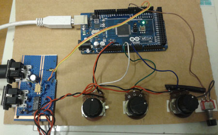
Midi Merging Analog Controller
In the mock up here, the MIDI OUT is connected to TX2, MIDI IN to RX2 and 3 analog pots are connected between +5V and Ground and to analog inputs AN0, AN1 and AN2. There is also a trigger push button.
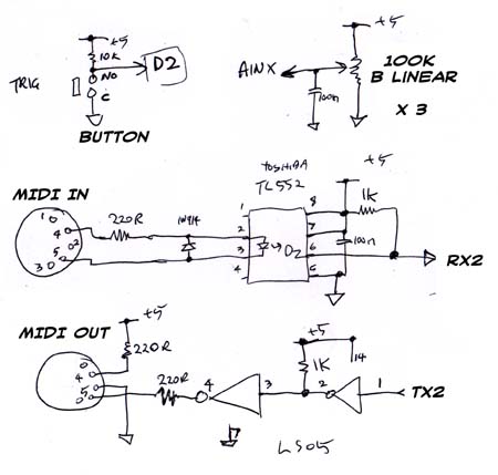
The MIDI I/O hardware is the way it was done in Roland product in the late 80s. Uses a Toshiba TL552 optocoupler on the MIDI INPUT and 74LS05 open collector in the MIDI OUT circuit. This isolates the Arduino board from the hostile outside world. When powering the system, note that Roland 9VDC power adapters have -ve on the center pin, whereas Arduino is the opposite and has +ve on that pin.
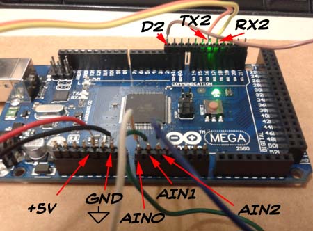
The MIDI I/O and Analog controllers are from an old previous project.
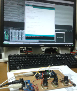
The Midi Merging Analog Controller Source Code
The MIDI IN code is not actually doing a complete merge as found in a Roland A-50 or A-880. It is doing a simpler combining the MIDI IN with the generated controller messages. This assumes the controllers being generated in this unit are not also coming in via MIDI IN. In our case we have a very old and simple Roland PC-180 MIDI Keyboard Controller.
MIDI IN has any Active Sensing and Running Status removed, and marks when whole messages have been received and retransmitted. Between MIDI IN messages, the 3 controllers are read and averaged with their previous values and output as MIDI control messages, if they have changed.
In the sending of the MIDI OUT, Running Status is re-introduced by not sending the MIDI command if it has not changed.
Default controller midi channel is 1, however, once MIDI IN messages are received, the channel of those messages is used. It is assumed that MIDI IN data is on a single MIDI channel, and not the output of a multichanel sequence.
The MIDI Controller numbers used are hard coded in this source. Active Sensing is not reintroduced in this version. A textDump function to the message window is included for debugging the MIDI messages.
This is the Mockup source code of the system in the photos.
Demo Video of Arduino Midi Merging Controller
A brief demo controlling some demo and free VST synthesisers that have MIDI Learn mode to assign controllers to screen controls.
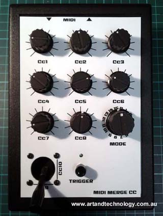
The system can be expanded to up to 16 controllers by adding more potentiometers, and modifying the code. Mounting the system in a robust enclosure is also required.
And this is a prototype controller we are working on:
References
Some books that may be useful:
Home
Copyright © 1995-2023 Art & Technology. All rights reserved.
No reproduction is permitted without explicit written permission.
|
|


